GEOTECHNICAL ENGINEERING1
SLOUGH
HomeGround improvementVibrocompaction design

Vibrocompaction Design for Slough Sites

Sound ground. Sound decisions.

LEARN MORE

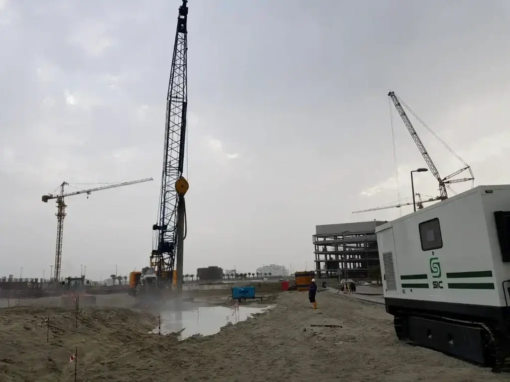
A recent three-storey commercial build near Slough Trading Estate hit a patch of loose river terrace gravels at 3.5 metres. The piling contractor called us before mobilising the rig. We ran a rapid-response CPT survey that afternoon, correlated the cone resistance data with the borehole logs, and delivered a vibrocompaction design within 48 hours. That kind of turnaround matters when the piling crew is on standby and the client needs a buildable solution. Slough sits on a complex sequence of Taplow Gravels overlying London Clay, and the gravels can vary from dense to dangerously loose within a single site boundary. Our design approach combines field data from CPT testing with grain-size analysis from disturbed samples, ensuring the stone column grid and probe energy are matched to the actual particle distribution, not just an assumed profile.

Vibrocompaction in Slough gravels demands probe spacing tighter than 2.2 metres when fines content exceeds eight percent — wider grids consistently underperform.
Our service areas

Scope of work

The Taplow Gravels underlying Slough date from an interglacial Thames terrace. They are typically sandy, sub-angular flint gravels with occasional silt lenses, and Standard Penetration Test N-values can swing from 8 to 35 in a vertical metre. That variability makes generic compaction recipes unreliable. Our design process starts with a high-resolution SPT drilling campaign to map the loose zones, followed by laboratory gradation curves that determine the suitability for vibratory compaction. We specify probe type, spacing on a triangular grid, amperage thresholds, and stage-by-stage lift thickness based on the fines content. When the silt fraction exceeds twelve percent, we model pore pressure dissipation rates to decide whether vibro replacement with stone columns is a more effective mechanism than pure densification. Every design is signed off by a Chartered Engineer and referenced to BS EN 1997-1, with working platform requirements clearly stated for the specialist contractor.
Vibrocompaction Design for Slough Sites
Technical reference — Slough

Local geotechnical context

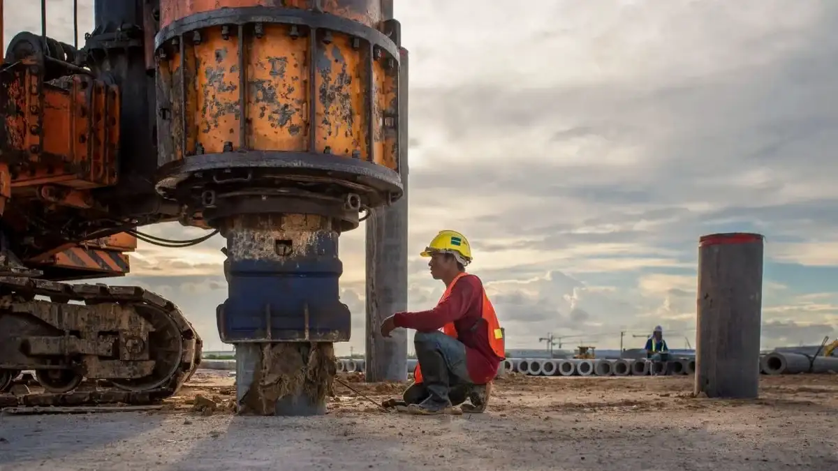
The deep vibrator rig weighs upwards of 45 tonnes and exerts dynamic forces that can destabilise adjacent services if the influence radius isn't calculated correctly. In Slough's industrial corridors, where gas mains, fibre optics, and high-voltage cables run at shallow depth beneath the pavement, we measure peak particle velocity at the nearest utility within the design phase itself. Loose saturated gravels in this area carry a moderate liquefaction susceptibility under cyclic loading, and the vibrocompaction process itself can trigger temporary pore pressure build-up. We specify hold points in the compaction sequence, maintaining vibration pauses until excess pore pressure dissipates below ten percent of the initial effective stress. This sequencing is documented on the method statement and cross-referenced with real-time CPT verification after every third probe location.

Need a geotechnical assessment?

Reply within 24h.

Email: contact@geotechnical-engineering1.com

Relevant standards

BS EN 1997-1:2004 + UK National Annex, BS 5930:2015 + A1:2020, ICE Specification for Ground Treatment (2nd Edition)

Reference parameters

ParameterTypical value
Target relative density≥ 70% (BS EN 1997-1)
Probe spacing (triangular grid)1.8 – 2.4 m
Max treatment depth18 m below working platform
Fines content limit (pure densification)< 12% passing 75 µm
Post-treatment verificationCPT + SPT correlation
Working platform bearing capacity≥ 35 kPa (granular)
Design settlement criterion< 25 mm differential

Common questions

What is the typical cost range for vibrocompaction design on a Slough site?

For a standalone design package covering a plot up to 800 m², including pre-treatment CPT profiling, laboratory grain-size curves, the design report, and post-treatment verification, the fee typically falls between £1,170 and £3,670. The spread depends on the number of CPT soundings required, the depth of the loose zone, and whether pore pressure dissipation modelling is needed for higher silt fractions.

How do Taplow Gravels respond to vibratory compaction?

They generally densify well because the gravel clasts are sub-angular and strong, with relatively low silt content in the cleaner horizons. The challenge is the interbedded silt lenses: if a continuous silt layer overlies a gravel unit, vibration energy reflects back and the gravel beneath remains untreated. We map those lenses with closely spaced CPT soundings before finalising the probe grid, and sometimes switch to a bottom-feed stone column approach where the silt seam is thicker than 400 mm.

What verification method does BS EN 1997 require after vibrocompaction?

BS EN 1997-1, via the UK National Annex, requires direct verification that the design relative density or cone resistance has been achieved. The accepted methods are CPT, SPT, or a combination of both, with a minimum of one test location per 200 m² of treated area, positioned at the centroid of the compaction grid where improvement is statistically weakest. We also run zone load tests when the foundation imposes high bearing pressures.

Can vibrocompaction be used close to existing buildings in Slough town centre?

It can, but the vibration monitoring protocol becomes the controlling document. We set peak particle velocity limits at 5 mm/s for listed structures and 10 mm/s for modern framed buildings, measured with triaxial geophones fixed to the nearest foundation. The compaction sequence is staggered so no probe fires within 8 metres of the building until the far-field grid is complete, creating a densified buffer that attenuates ground-borne vibration.

How long does the design process take from instruction to issue?

If the CPT and SPT data already exist, we can turn around the design package in three to four working days. When we need to mobilise our own CPT rig in Slough, add one day for fieldwork and one day for data processing. Complex sites requiring pore pressure dissipation analysis or stone column hybrid design may extend the timeline to seven working days in total.

Location and service area

We serve projects in Slough and surrounding areas.

View larger map