GEOTECHNICAL ENGINEERING1
SLOUGH
HomeGeophysicsSeismic tomography (refraction/reflection)

Seismic Tomography Surveys in Slough: Uncovering Hidden Ground Conditions

Sound ground. Sound decisions.

LEARN MORE

The geology beneath Slough can shift dramatically within a single postcode. We see this all the time when crossing from the gravel terraces near the Jubilee River over to the London Clay formation that dominates the northern reaches of the town. Where one site offers firm bearing just a few metres down, another hides deep softened clay or buried channels that standard boreholes miss entirely. That contrast is why a seismic tomography survey becomes the logical step before finalising foundation design. By measuring the velocity of compression and shear waves through the ground, we build a continuous cross-section of the subsurface. This approach bridges the gap between isolated test pits and the full picture a structural engineer needs, especially in Slough’s redeveloped industrial zones where historical fill is common and unpredictable.

A seismic velocity section reveals what a grid of boreholes cannot: the continuous profile of the ground, including the hidden dissolution features common in the Slough chalk.
Our service areas

Scope of work

A common mistake we encounter in Slough is relying solely on a grid of boreholes and assuming the strata run straight between them. On a recent logistics depot off the A4, the client had three boreholes showing competent chalk at 6 metres, but a 12-metre-wide dissolution feature sat undetected in the middle of the pad. A refraction survey would have flagged the velocity drop immediately. That kind of oversight leads to differential settlement and expensive remedial work. Our seismic profiles detect lateral velocity contrasts that point to voids, fractured chalk, or pockets of loose fill. When the target is deeper, reflection processing maps the chalk bedrock surface continuously, something a CPT test alone cannot achieve. For shallow infrastructure, we combine the seismic data with a plate load test to correlate dynamic stiffness with the actual deformation modulus measured at foundation level.
Seismic Tomography Surveys in Slough: Uncovering Hidden Ground Conditions
Technical reference — Slough

Local geotechnical context

Slough sits at approximately 32 metres above sea level on a complex mix of Thames Valley drift deposits and the underlying Seaford Chalk Formation. The chalk here is notorious for containing solution pipes and infilled sinkholes, a legacy of periglacial weathering. If a structure is designed without seeing these features, the risk isn't just a crack in the slab; it’s a sudden loss of bearing capacity in one corner of the building. The hydrogeology adds another layer of complexity, as perched water tables within the gravels can obscure the true bedrock reflection in a radargram but remain transparent to a properly shot seismic line. Ignoring these conditions during a warehouse extension or a multi-storey residential build on the Bath Road corridor is a gamble that rarely pays off, often triggering years of litigation over performance gaps in the finished structure.

Need a geotechnical assessment?

Reply within 24h.

Email: contact@geotechnical-engineering1.com

Relevant standards

BS 5930:2015+A1:2020 – Code of practice for ground investigations, Eurocode 7: Geotechnical design – Part 2: Ground investigation and testing (BS EN 1997-2:2007), BS EN ISO 22475-1:2021 – Geotechnical investigation and testing – Sampling methods and groundwater measurements

Reference parameters

ParameterTypical value
Survey methodSeismic refraction and reflection (P-wave and S-wave)
Depth of investigationRefraction: 15-30 m; Reflection: up to 100 m depending on source energy
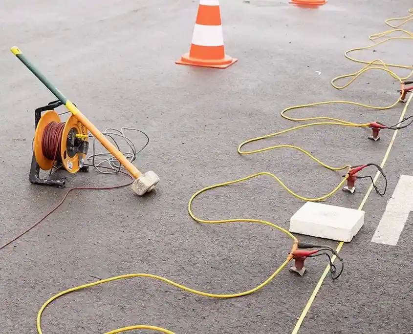
Source typeAccelerated weight drop or sledgehammer with stacking
Geophone spacing2 m to 5 m depending on target resolution
Data processingTomographic inversion, common mid-point stack, time migration
DeliverablesP-wave velocity tomograms, interpreted geological cross-sections, bedrock contour maps
Applicable standardBS 5930:2015+A1:2020, Eurocode 7 (BS EN 1997-2:2007)

Common questions

How much does a seismic refraction survey cost for a typical Slough site?

For a standard refraction line of 100 to 150 metres, the cost in Slough typically ranges from £2,280 to £4,050. The final figure depends on access conditions, the required depth of penetration, and whether you need P-wave only or combined P- and S-wave acquisition. We can provide a firm quotation once we review the site layout and your specific engineering questions.

Can seismic surveys work effectively in the built-up areas of Slough?

Yes, but we have to be smart about it. The industrial estates and residential roads around Slough generate background noise that can degrade conventional seismic records. We compensate by using a high-energy accelerated weight drop source and vertical stacking of multiple impacts to boost the signal-to-noise ratio. The London Clay at the surface also helps dampen some of the cultural noise, which is an advantage here compared to surveys on exposed rock.

What is the difference between seismic refraction and reflection for mapping the Slough chalk?

Refraction is excellent for mapping the top of competent chalk when the velocity increases with depth, which is the typical case in Slough. It gives us a clear line on the bedrock surface and any gross soft zones. Reflection comes into its own when we need to image structural details within the chalk, like the steep-sided dissolution pipes that can punch right down into the formation. For a piled foundation design close to the Jubilee River corridor, we often recommend running both methods along the same line to cross-validate the interpretation.

Location and service area

We serve projects in Slough and surrounding areas.

View larger map