GEOTECHNICAL ENGINEERING1
SLOUGH
HomeGeophysicsElectrical resistivity / VES (Vertical Electrical Sounding)

Electrical Resistivity Testing and Vertical Electrical Sounding in Slough

Sound ground. Sound decisions.

LEARN MORE

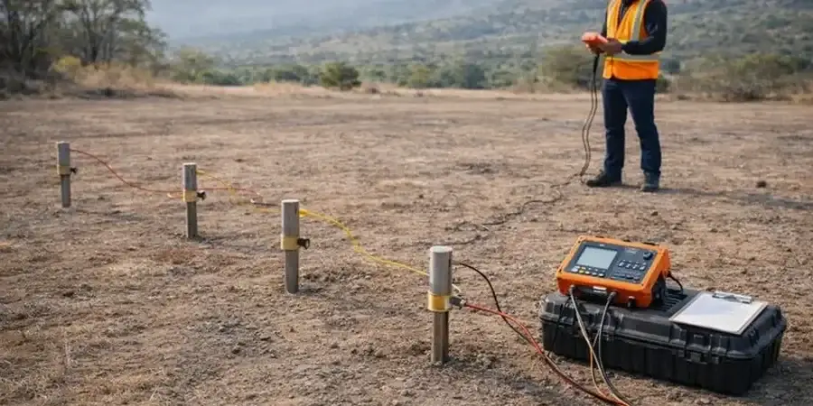
Slough’s expansion from a minor coaching stop to a major industrial hub fundamentally altered how we interact with the underlying ground. The historical brickmaking industry left a legacy of clay pits and variable backfill across the borough, while the natural geology—dominated by the stiff, overconsolidated London Clay Formation—presents subtle but critical mapping challenges. A standard borehole tells you what happens at a single point, but it rarely captures lateral transitions between the clay, underlying Lambeth Group sands, and perched water tables that can derail excavation budgets. For linear infrastructure and brownfield redevelopment, we deploy electrical resistivity tomography and Vertical Electrical Sounding to build a continuous resistivity model of the subsurface. When combined with targeted Spt Drilling for physical validation, the resulting ground model provides the spatial resolution that spot sampling alone cannot deliver.

Mapping resistivity contrasts across the London Clay reveals perched water and sand lenses that conventional boreholes can miss between sampling points.
Our service areas

Scope of work

A common misjudgment in Slough is assuming that the London Clay behaves as a uniform, homogeneous mass simply because it appears consistent in a trial pit. In reality, the clay’s resistivity can shift dramatically depending on its moisture content, fissuring, and the presence of granular partings or silt laminae. Contractors who rely solely on intrusive investigation occasionally miss a perched water pocket trapped within a weathered zone until the excavator breaks through. That discovery stops work, triggers re-design, and inflates the temporary works budget. Electrical resistivity surveys measure how easily the ground transmits a current, with low resistivity typically indicating clay-rich or saturated materials, and higher resistivity suggesting drier sands or gravels. The technique lets us map these contrasts continuously across a site, so you know where to expect groundwater ingress before you mobilize dewatering pumps or design retaining structures. This approach ties directly into the desk study requirements of BS 5930:2015+A1:2020, ensuring that the conceptual ground model is supported by geophysical evidence rather than interpolation alone.
Electrical Resistivity Testing and Vertical Electrical Sounding in Slough
Technical reference — Slough

Local geotechnical context

BS 5930:2015+A1:2020 and BS EN 1997-2:2007 establish the framework for combining geophysical and intrusive investigation, and in Slough the rationale extends beyond simple code compliance. Parts of the borough sit over infilled palaeochannels and former brickearth workings where the contrast between natural clay and anthropogenic fill carries a resistivity signature that can be identified with a properly executed survey. Missing a buried channel that connects to a gravel aquifer means your excavation design underestimates groundwater flow; the consequence is a flooded cut, delays, and emergency dewatering costs that could have been avoided. The risk amplifies on sites adjacent to the Jubilee River or the Slough Arm of the Grand Union Canal, where canal leakage and river-aquifer interaction create complex, seasonally variable saturation profiles. Resistivity data gives the engineer a basis for designing cut-off walls or dewatering arrays with realistic hydraulic parameters rather than conservative assumptions that inflate the construction budget.

Need a geotechnical assessment?

Reply within 24h.

Email: contact@geotechnical-engineering1.com

Relevant standards

BS 5930:2015+A1:2020 – Code of practice for ground investigations, BS EN 1997-2:2007 (Eurocode 7) – Ground investigation and testing, BS 8574:2014 – Code of practice for the management of geotechnical data for ground models

Reference parameters

ParameterTypical value
Typical Survey Depth (VES)1.5 to 60 m below ground level
Electrode ArrayWenner and Schlumberger configurations
Measured PropertyApparent electrical resistivity (Ω·m)
Data Output1D resistivity soundings and 2D resistivity imaging (ERT)
Target AnomaliesClay-sand interfaces, perched water, buried channels, backfill extent
Inversion SoftwareRes2DInv or equivalent solid inversion
Reporting StandardBS 5930:2015+A1:2020, Eurocode 7 (BS EN 1997-2:2007)

Common questions

What depth of investigation can resistivity surveys achieve in the London Clay around Slough?

Vertical Electrical Sounding (VES) typically reaches depths between 1.5 and 60 metres below ground level, depending on the electrode spread length and the local resistivity structure. In the London Clay, the relatively low resistivity can limit maximum penetration compared to dry gravels, but the 30 to 50-metre range is routinely achievable. For deeper targets within the Lambeth Group or Chalk, we adjust the array geometry and may recommend a hybrid approach with complementary geophysical methods.

How much does an electrical resistivity survey cost for a typical site in Slough?

A resistivity survey in Slough generally ranges from £460 to £760 for a targeted VES sounding or a single 2D profile of moderate length. The final cost depends on the number of soundings, the profile length, the terrain accessibility, and the reporting requirements. We provide a fixed-price proposal after reviewing the site plan and the investigation objectives.

Can resistivity identify the boundary between the London Clay and the underlying Lambeth Group sands?

Yes, the resistivity contrast between the low-resistivity London Clay (typically 10-40 Ω·m) and the more resistive Lambeth Group sands and gravels (often exceeding 80-100 Ω·m) produces a distinct geophysical marker. We calibrate the interpreted boundary against existing borehole logs or window samples, then extrapolate the interface across the survey line. This is particularly useful on sites where the depth to the Lambeth Group varies because of buried channels or structural deformation.

Location and service area

We serve projects in Slough and surrounding areas.

View larger map