GEOTECHNICAL ENGINEERING1
SLOUGH
HomeUnderground ExcavationsGeotechnical design of deep excavations

Deep Excavation Design in Slough: Ground Conditions That Demand Precision

Sound ground. Sound decisions.

LEARN MORE

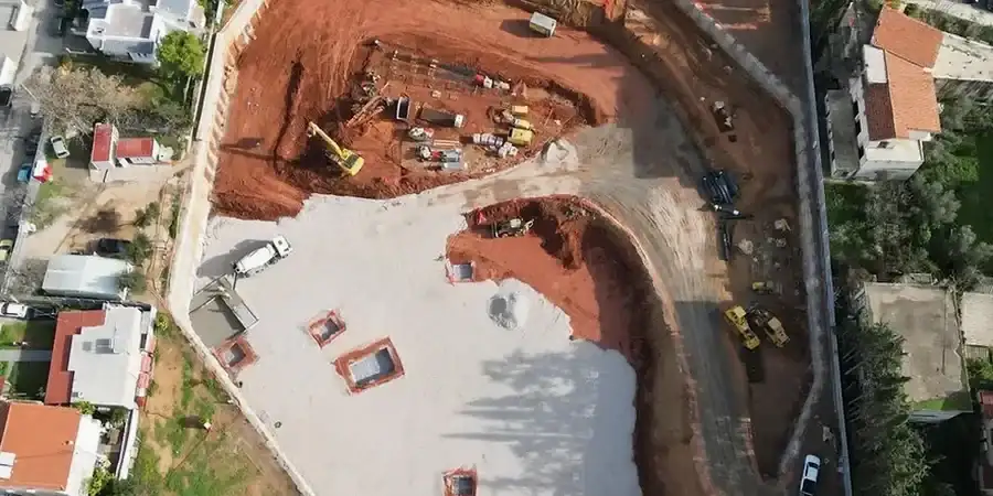
Slough sits barely 32 metres above sea level, atop the London Clay Formation that has shaped construction across the Thames Basin for decades. This stiff, overconsolidated clay looks competent in a trial pit, yet it weathers rapidly when exposed, and its in-situ stress history means any deep excavation here behaves differently than textbook predictions suggest. We design temporary and permanent shoring systems based on ground investigation data interpreted through Eurocode 7 (BS EN 1997-1:2004) and BS 5930, factoring in the local groundwater regime that often surprises contractors who assume dry conditions below 3 metres. For projects near the Jubilee River or within the Slough Trading Estate, where basements push 8 to 12 metres deep, the interaction between excavation geometry and adjacent foundation loads becomes critical. Our team models staged construction sequences using finite element analysis, verifying wall deflections and strut forces against monitoring data collected on previous Slough projects. When the client needs a faster site characterisation before the main investigation, we often run a complementary test pit programme to log the weathered zone thickness and confirm the depth to the gravel layer that dictates dewatering strategy.

London Clay isn't one material—it's a profile. Designing for Slough means parameterising weathered crust, intact clay, and transition zone separately.
Our service areas

Scope of work

A mistake we see repeatedly across Slough and the wider Berkshire area is designers treating the London Clay as a homogeneous, isotropic material. The upper 2 to 3 metres are typically weathered, fissured, and softened by seasonal moisture fluctuation—design parameters valid at 8 metres depth simply do not apply near the surface. This misjudgment leads to undersized waling beams and unexpected wall movements during the early excavation stages. Our design methodology separates the ground profile into geotechnical units with distinct stiffness and strength envelopes, calibrated against laboratory triaxial data and in-situ pressuremeter results. We specify undrained shear strength profiles that reflect the clay’s geological history, not just index tests. When the excavation approaches the water-bearing Lambeth Group sands beneath the clay, we incorporate hydraulic uplift checks and base heave assessments that comply with CIRIA C760 guidance. For sites where the retained height exceeds 6 metres and the adjacent infrastructure includes sensitive rail corridors or Victorian masonry, we recommend integrating inclinometer and load cell monitoring as part of the observational method, triggering contingency measures if displacements trend beyond the agreed threshold.
Deep Excavation Design in Slough: Ground Conditions That Demand Precision
Technical reference — Slough

Local geotechnical context

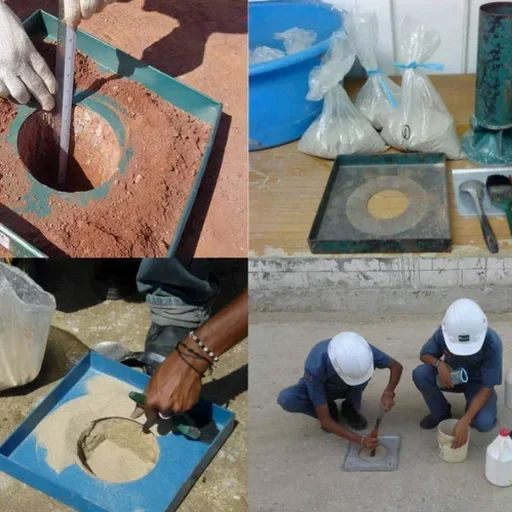
In Slough, many sites we inspect sit on a thin gravel lens between the London Clay and the Lambeth Group—a perched aquifer that nobody anticipated until the first bucket of water flooded the excavation. This isn’t a rare occurrence; it’s a pattern across the town’s geology, particularly east of the M4 towards Langley. A design that ignores this gravel risks base instability, piping, and sudden inflow that can undermine adjacent roadways or buried utilities. We run seepage analyses as a standard deliverable, not an optional extra, and specify cut-off requirements that match the actual hydraulic conductivity measured through in-situ permeability tests rather than generic textbook values. Another risk we address early is the proximity of neighbouring buildings with shallow strip footings—common in Slough’s older residential streets and industrial estates. Ground loss from wall deformation can translate directly into settlement damage, so our deflection predictions include a damage classification assessment following Burland’s methodology, giving the contractor clear trigger levels before the first shovel hits the ground.

Need a geotechnical assessment?

Reply within 24h.

Email: contact@geotechnical-engineering1.com

Relevant standards

BS EN 1997-1:2004 (Eurocode 7: Geotechnical design – Part 1: General rules), BS 5930:2015 + A1:2020 (Code of practice for ground investigations), BS EN 1997-2:2007 (Eurocode 7: Ground investigation and testing), CIRIA C760 (Guidance on embedded retaining wall design), BS 5975:2019 (Code of practice for temporary works procedures)

Reference parameters

ParameterTypical value
Typical excavation depth range (Slough)4 to 14 metres below ground level
Design standardBS EN 1997-1:2004 + UK National Annex
Ground investigation codeBS 5930:2015 + A1:2020
Retaining wall types analysedSecant piles, diaphragm walls, sheet piles, king post
Groundwater control guidanceCIRIA C750 and C760
Analysis methodFEM (Plaxis 2D/3D) + limit equilibrium verification
Design life (temporary works)Typically 18–36 months per BS 5975
Adjacent infrastructure deflection limits10–25 mm depending on asset owner criteria

Common questions

What is the typical cost range for geotechnical design of a deep excavation in Slough?

Design fees depend heavily on excavation depth, ground complexity, and the number of construction stages analysed. For a typical Slough project with 6 to 10 metres retained height, our design package falls between £1,460 and £6,960. This covers parameter selection, wall design, strut/anchor design, base heave checks, and movement predictions. An unusually deep excavation or one requiring 3D finite element analysis for complex geometry will sit toward the upper end of that range.

How does London Clay affect deep excavation design in Slough?

London Clay in Slough is stiff and overconsolidated, which means it can stand unsupported for short periods but develops significant horizontal stresses over time. Its upper weathered zone is weaker and more permeable than the intact material below. We parameterise these layers separately, using undrained shear strength profiles from triaxial testing and in-situ pressuremeter data, and we account for softening that occurs when the clay is exposed to air and water during construction.

Which retaining wall types do you design for Slough ground conditions?

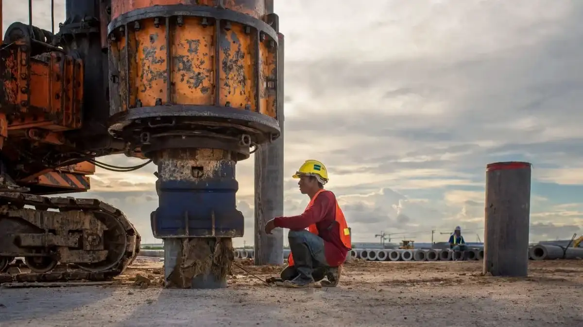
We design secant pile walls, contiguous pile walls, diaphragm walls, sheet pile walls, and king post walls. The choice depends on excavation depth, groundwater conditions, and proximity to adjacent structures. In Slough’s London Clay, secant piles are common for basements where water cut-off is required; sheet piles work well for shallower excavations in the trading estate where vibration limits permit driving.

Do you handle groundwater control as part of the excavation design?

Yes, groundwater control is integral to every design we produce. We map the local hydrogeology—including the perched gravels common in Slough—and specify dewatering requirements, cut-off depths, and base heave checks that account for pore water pressure. Our designs reference CIRIA C750 and C760, and we size sumps, well points, or deep wells based on in-situ permeability test results.

What deliverables do I receive with a deep excavation design package?

You receive a design report with geotechnical parameter derivation, wall and support element schedules, staged excavation sequence drawings, ground movement predictions, and a construction monitoring specification. For temporary works, the package aligns with BS 5975 requirements so your temporary works coordinator can review and approve without chasing missing information.

Location and service area

We serve projects in Slough and surrounding areas.

View larger map